With the basic x-axis assembly constructed it was time to figure out how best to mount the motor and idler pully to the assembly. My original basic x-asis ends had not taken this into consideration. It was now time to address this!
I usually start with a dimensioned drawing. I hand draw on grid paper sometimes. It allows me to watch TV at the same time! I've found starting with a drawing gives me a good idea of scale and proportion of the parts, and gives me a plan to work to, saving time and reducing rework. Here's my working drawing:
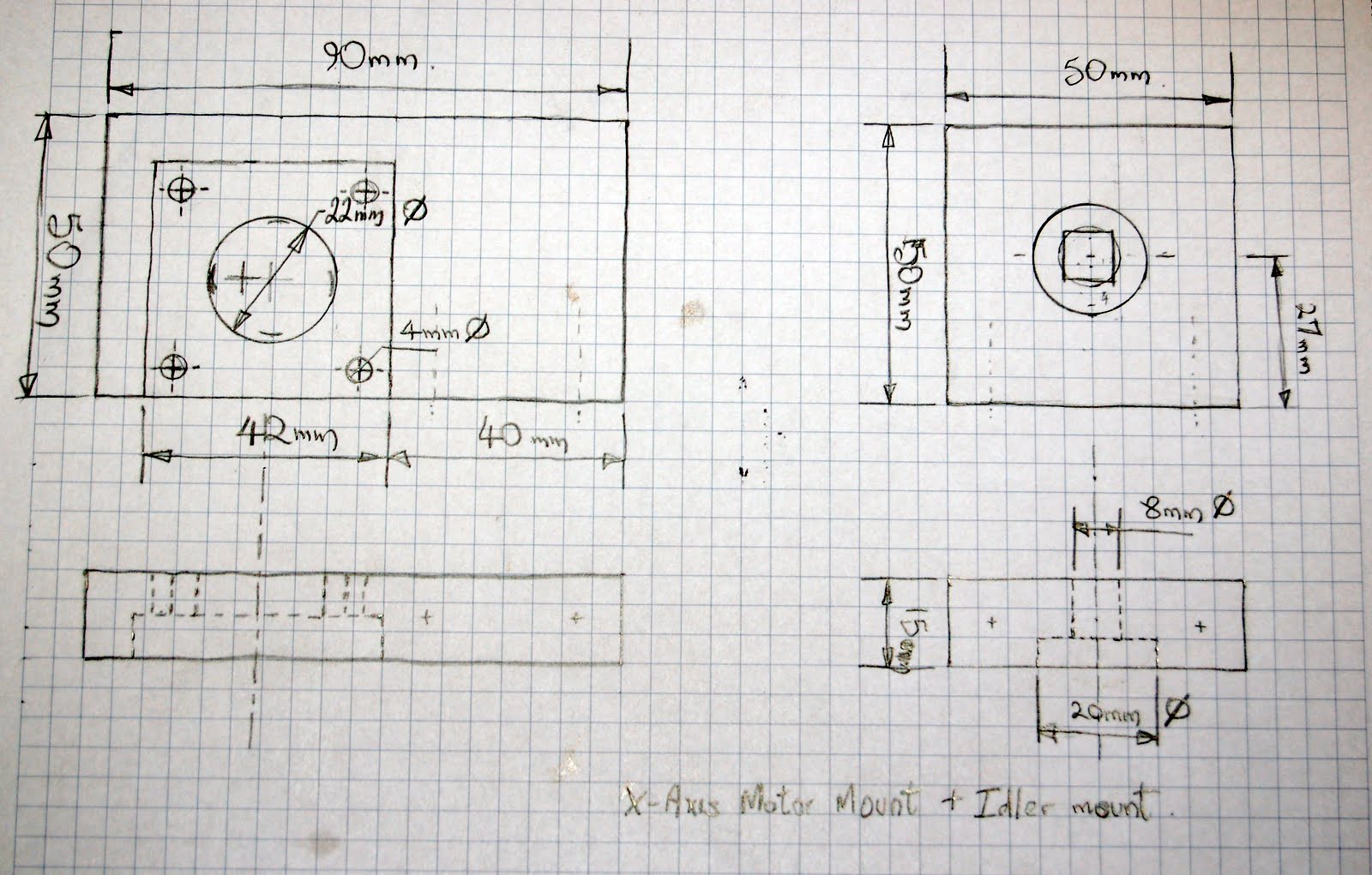
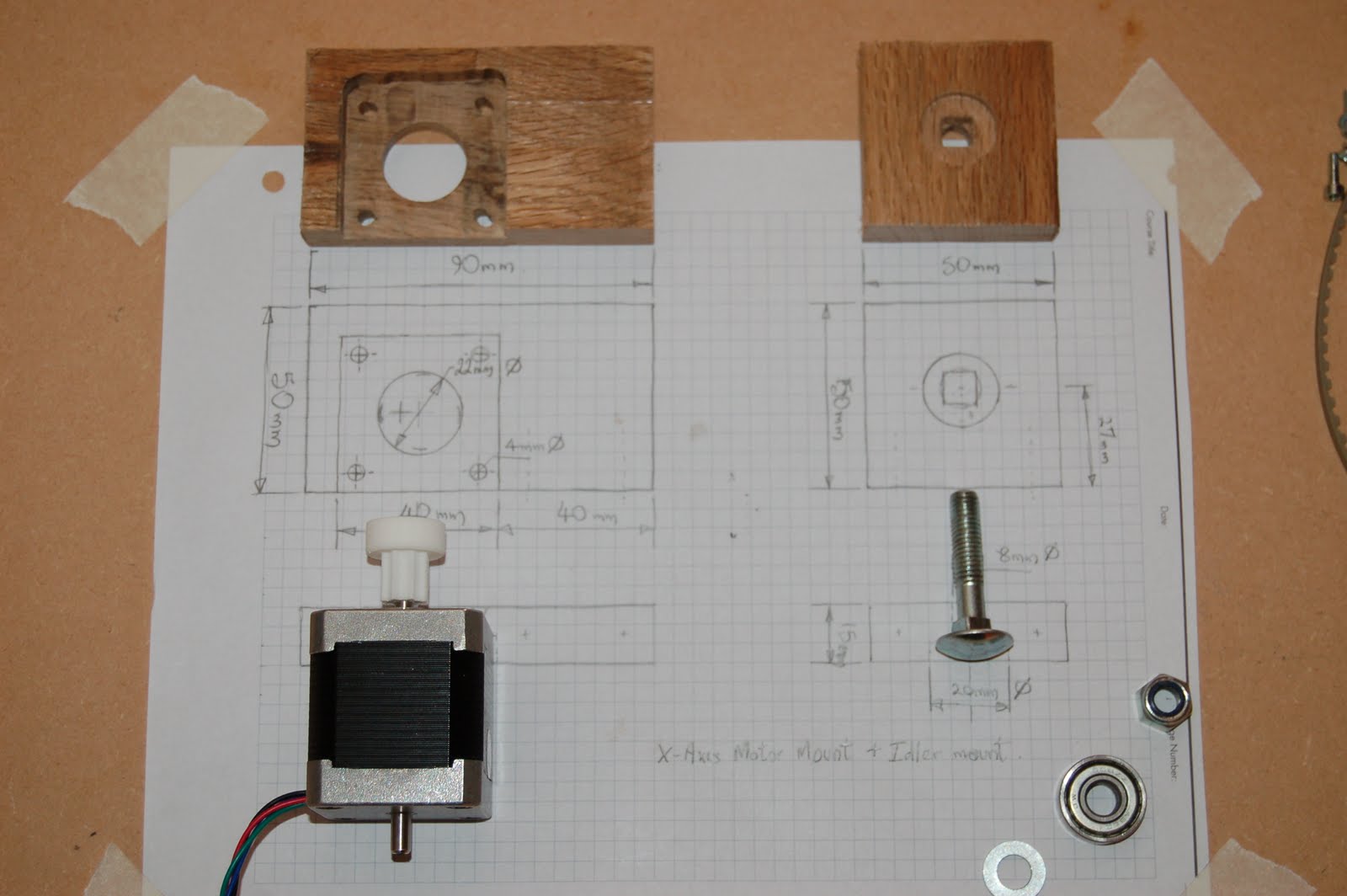
Two pieces were cut, drilled and routed to the desired shape. The routed recess in the left piece was to receive the motor, providing greater support for the motor, while still leaving the full thickness of the board to maintain strenght in the block. Sinking the motor into the block also allowed the shaft to protrude further on the other side. The square block had an 8+mm hole drilled through, and a 20mm hole sunk half way to receive the head of an 8mm carriage bold. I filed out the center to a square shape to receive the square part of the carriage bold shaft. Note: The hole in the 50x50mm block is higher than center, so the base of the idle bearing is aligned with the base of the drive pulley on the stepper motor, allowing the drive belt to run perfectly horizontally.


These pictures (above) show a trial fitting of the stepper motor to it's mounting block, and the idler pulley (skateboard bearing) sandwitched between various washers, all held on by an m8 nylock nut.
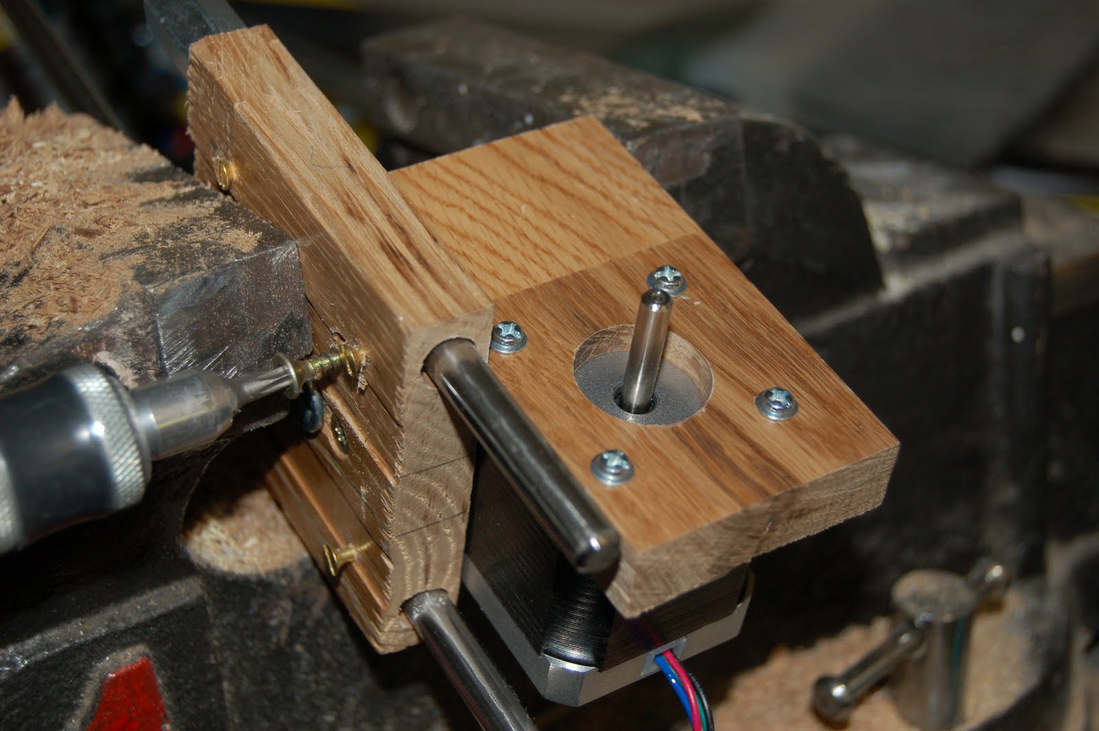

Securing the motor mount block to the base was done with two screws from underneath. The idler block, at the far end of the x-axes assembly was also held in the same way, but their allignment was checked before the second pilot hole and screw was fitted to each. (They are assembled dry at the moment, but I'll glue and screw them for a stronger and more perminent assembly at a later point.)
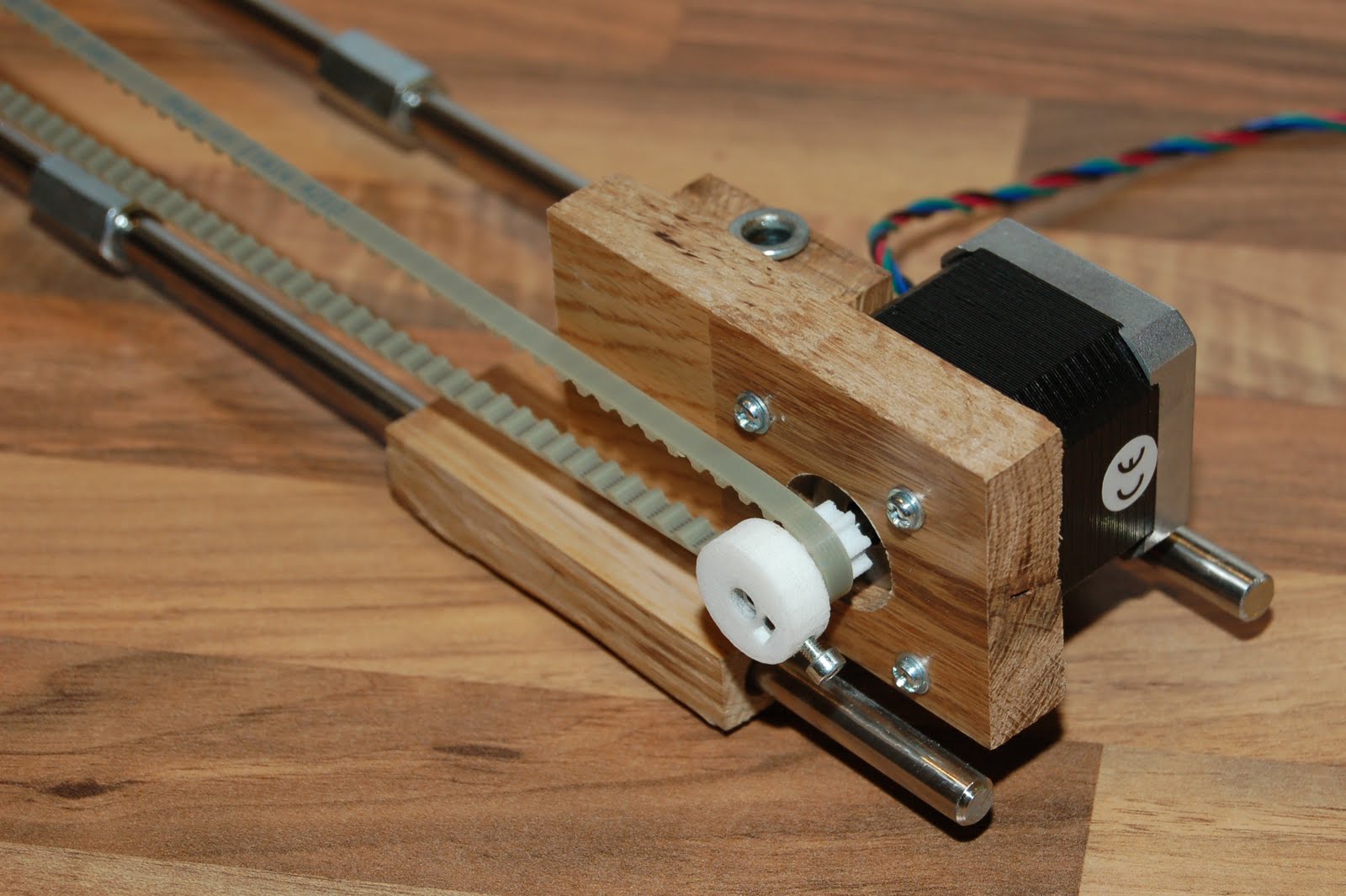

Here (above) are the 'end' and 'motor' mounting blocks, now in position on the x-axis assembly. I was limited in the overhank I could achieve for the belt because of my assembly technique (the two screws from underneath). This may impact on my extruder design, but I'm not worried at the moment... haven't got to that yet! :-)
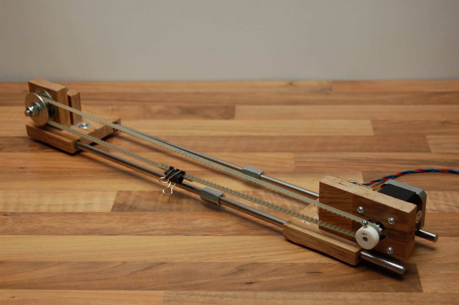
And finally, for this post... the completed x-axis assembly!

Thanks for visiting.
No comments:
Post a Comment
Note: Only a member of this blog may post a comment.