...digital fabrication meets the ancient art of iron casting.

Sculpture design, casting and photos by Lar O'Toole, Visual Artist.
In preparation for his participation in the IRON-R 18 Project (July 2018), a friend of mine, Lar O'Toole approached me with a design he wanted me to 3d print. The 3d printed objects would be models or 'patterns' for use in the iron casting workshop (IRON-R 18). In assessing the Sketchup 3d model file he provided, there were a number of issues evident, which would lead to slicing (g-code generation) issues and a poor 3d print. These issues were not insurmountable, but with a very tight time deadline, I took on the challenge of re-drawing the model from scratch. This would give a clean STL file (format required for 3d prining) and a resulting smooth 3d print.
My blog is in general, 3d printing focused, so I thought it worth expanding on this aspect of Lar's undertaking, but I've also embraced the opportunity to share Lar's experience of the journey from digitally sketched idea to the final and very impressive iron castings.
Lar's design is an interesting interpretation of a Ptolemaic Geocentric style model of the Universe. A central sphere (the Earth), with expanding concentric circles, but with the added twist of 'orbit' circles retreating in steps, as if to reveal and present the central sphere. A second similar but slightly different copy of the sculpture was also produced, gesturing to the ideas of Copernicus and his Copernican Heliocentric, sun centered model. The pieces are similar but different, as observed in the photo above, with the orbiting moon distinguishing the Copernican model.

3d model in Sketchup, (180mm approx diam.)
In re-drawing the design I concluded the best approach was to aim towards a "half-model", but to visualise the concentric 'circles' as cylinders, rather than spheres. Once I hit on this construction method, it came together quite quickly in Sketchup. Concentric sphere segments would be too challenging in Sketchup and better suited to something like Fusion360 of a solid modelling package.
The other and inner spherical shapes, were produced using the "follow me" tool in Sketchup, using a semi-circle as the basic shape and sweeping it through an arc.
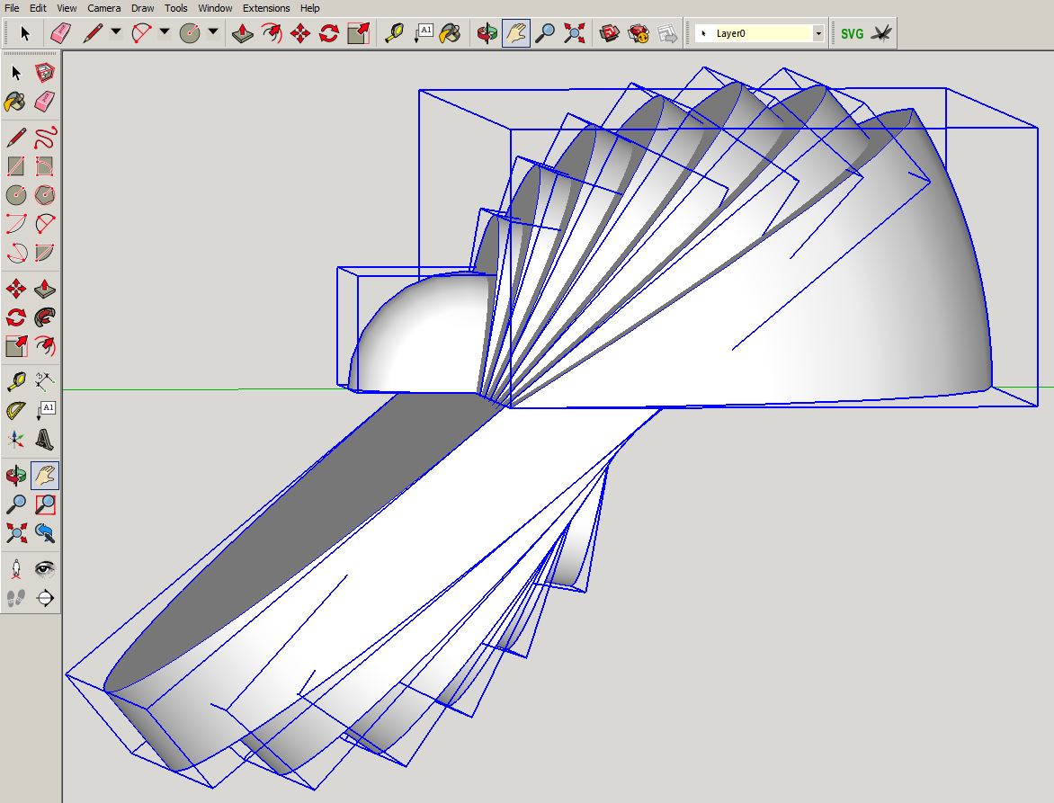
Above, concentric cylinders, rotated in steps are clearly visible. A small hemisphere (swepted semi-circle, using the 'follow me' tool) in the middle, and a sphere segment forms the other section.
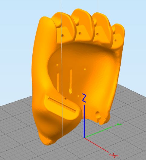
These multiple objects, pictured above, were exploded into their component elements (select all.. right-click, explode). Then the face of each step cylinder was "intersected with the model" (another right-click process), and all of the unwanted faces and lines were removed from the construction, revealing a clean half-model with a completely hollow inside (See view below showing internal hollow.).

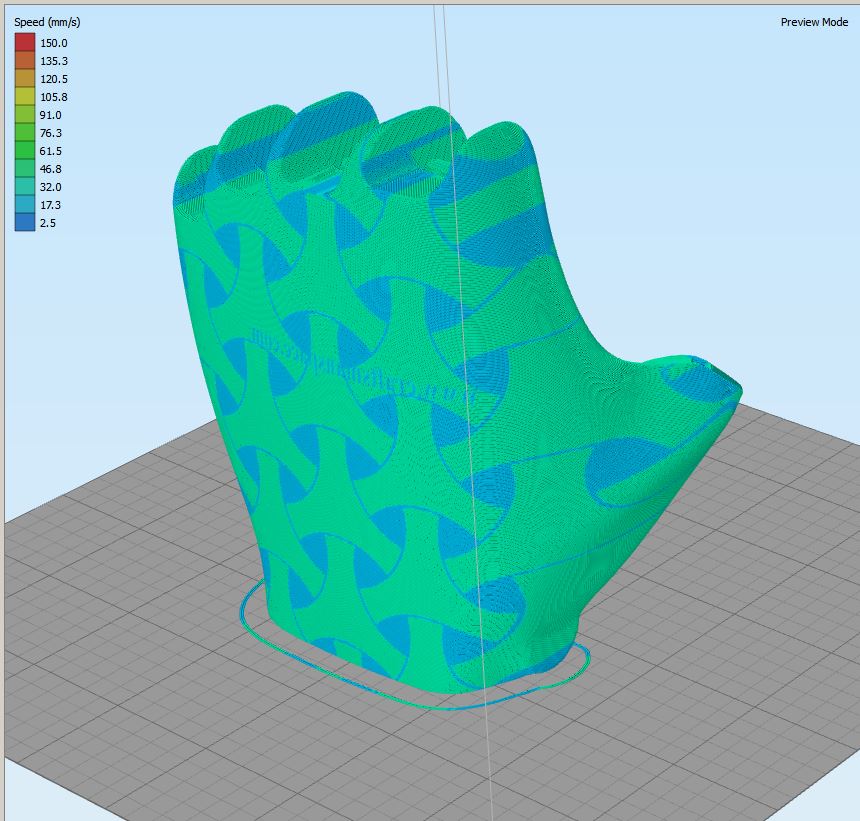
The 'half-model' was capped, producing a fully manifolded solid object, an essential requirement for 3d printing. Internal shapes or orphaned lines or surfaces will cause issues later when slicing for 3d printing. It was exported from Sketchup in STL format and sliced (in Simplify3d), producing the g-code necessary for 3d printing.
Slicing and Printing


For alignment and assembly of the two identical halves, I simply placed two holes in the model, and inserted wooden dowels for perfect assembly.


The Casting Process
Lar took things from here. I'm very grateful to him for sharing some photos of the process and providing explanations of the steps he followed. Pictures, as always, are worth a thousand words!
Smoothing of the model, was achieved by application of "Milliput" filler, a fast setting, non-shrinking epoxy putty. The surfaces were filled and sanded to a desired level of smoothness.


A box was built to hold the 'pattern' and it was bedded in red sand up to it's half-way line (picts below). A larger box than might be usual was made because of the final mass of poured object. The red sand was compacted and leveled and pockets removed near the edges to form registration tabs. A dusting of 'parting powder' was added to the top surface to prevent mould mix sticking to the red sand. The mould mix made of silica sand and special quick-setting resin & hardener mix, was added to form the half-mould. Once hardened (<2hrs), the box was removed and the red sand brushed off, box re-fitted and the top half of the mould formed.


Lar pointed out... "A small ball of wax was added to the edge of one of the pattern to represent a moon. The wax was removed from the mould before sealing it up."


Lar continues to explain... "One big gate was added to fill the mould, split into two runners as it reached the void, a 'bowl' carved at the base of the gate to allow the iron to pool and reduce the chance of air bubbles forming. Two risers were added on either side to allow air to escape. Dry graphite was used as a release agent. A mixture of graphite power and alcohol was brushed on the inside of the mould to stop the iron adhering to the sand, then the alcohol was burned off."
The focus of the workshop week was mastering the skills necessary to produce the moulds. The moulds were glued and steel banded and joints further sealed with fire proof sealant. Lar continues... "The 50+ moulds were transported to the National Sculpture Factory for the pour on Saturday. Here we attached pouring cups and chimneys to the moulds. the 'burn-in' of the cupola took about 40 minutes, then a charge of coke and iron were added and the first 'tap' was ready about 25min later. This time reduced to about 12 minutes as the cupola got hotter."


Lar: "The crucible held about 20-25kgs, but got heavier with each pour as slag and iron built up. There were about 15 pours in all over an 8hr period."
Temperatures well in excess of 1000 Degrees C are required to melt iron, This presents as spectacular lava-like pours into the awaiting moulds.


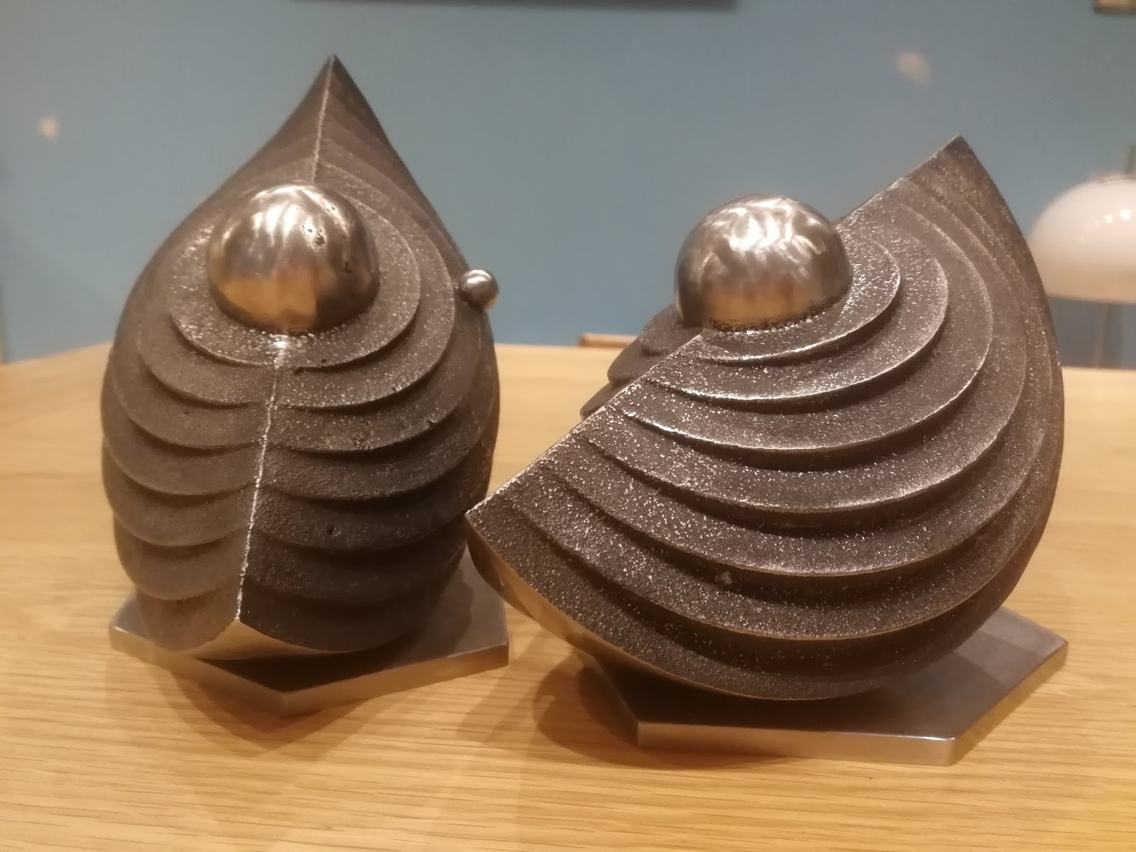
Lar rounded off presentation with stainless steel base plates. Fantastic results!
Lar had the vision to see the potential the digital 3d modelling medium might have to communicate his creative ideas, and the potential 3d printing might have to accelerate the preparation for casting, and the drive to want to explore the combination of the ancient skill of iron casting with the comparatively fledgling technology of 3d modelling and 3d printing. I was glad to have the opportunity to play a small part in this exploratory journey. Thanks Lar!
Ivor O'Shea
July 2018


